

Plastic extrusion is a high-volume manufacturing process known for producing continuous, uniform plastic products. A key factor in its success is the design and tooling involved in shaping raw plastic into finished products. It rewards designs that are built with how material actually flows, cools, and stabilizes in mind.
When design and tooling are aligned early, you get consistent output, predictable tolerances, and efficient production. When they are not, it results in rework, delays, and avoidable expense.
In this guide, we will explore the principles of plastic extrusion design and tooling and offer practical insights into how engineers and manufacturers create efficient, high-quality extrusion processes.
What Is Plastic Extrusion Design?
Plastic extrusion design refers to the planning and engineering of a product’s cross-sectional geometry so it can be manufactured efficiently through an extrusion process. Unlike other manufacturing methods, extrusion produces a continuous profile, meaning the shape remains consistent along the entire length of the part.
This process begins by feeding raw plastic material such as pellets, granules, flakes, or powders into an extruder. Inside the barrel, rotating screws and external heaters melt the material into a uniform molten state. The material is then pushed through a die that defines the final shape, and as it exits, it cools and solidifies into the finished profile.
The design phase determines whether that process runs smoothly or becomes a source of defects, delays, and added cost. A well-designed extrusion profile balances performance requirements with manufacturability, ensuring consistent output, stable dimensions, and minimal waste.
Understanding Plastic Extrusion Tooling
Plastic extrusion tooling includes all components used to shape and stabilize the molten material as it transitions into a finished product. The most critical element is the extrusion die, which defines the cross-sectional geometry of the profile.
Beyond the die, tooling also includes calibrators, cooling systems, pullers, and cutting equipment. Each plays a role in maintaining dimensional accuracy and surface quality after the material exits the die.
Tooling design directly impacts:
- Material flow consistency
- Dimensional tolerances
- Surface finish quality
- Production speed and scrap rates
Even small inefficiencies in tooling can result in long-term production issues. That is why tooling is not just about shaping the material but also about controlling how the material behaves under heat, pressure, and cooling conditions.
Key Considerations in Plastic Extrusion Design
Designing for plastic extrusion requires careful attention to how material flows, cools, and stabilizes. The following considerations have the biggest impact on performance and manufacturability.
Wall Thickness, Hollow Sections, & Radius Considerations
These three factors—wall thickness, hollow sections, and radius considerations—determine whether a profile runs cleanly or becomes a source of instability. Wall thickness, internal geometry, and corner transitions all influence how material flows through the die, how evenly it cools, and how the part holds its shape after extrusion. Get them right and production stays predictable; get them wrong and you introduce warping, dimensional drift, and avoidable scrap.
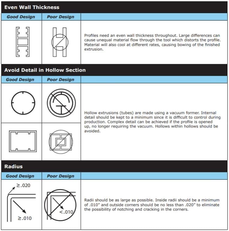
Even Wall Thickness
Profiles should maintain as consistent a wall thickness as possible. Significant variations create uneven material flow through the die, which leads to distortion, dimensional instability, and inconsistent output during long production runs. Thicker sections tend to flow slower and retain heat longer, while thinner areas cool faster, creating internal stress and shape deformation.
If variation is unavoidable, transitions should be gradual rather than abrupt. Sudden changes force the material to accelerate or decelerate too quickly, which disrupts flow balance and increases the likelihood of defects.
Design tip: Gradual transitions between thick and thin areas are far more stable than abrupt changes and help maintain consistent flow through the die.
Hollow Sections
Hollow extrusions such as tubes are typically formed using vacuum calibration, which relies on consistent external pressure to hold shape during cooling. Because of this process, internal complexity should be minimized. Features like internal ribs, tight cavities, or multi-channel hollows make it significantly harder to maintain dimensional control.
As complexity increases, so does the risk of uneven wall thickness, internal collapse, or variation along the length of the profile. These designs also require more advanced tooling, which increases cost and setup time.
Closed hollow shapes within other hollow shapes should be avoided whenever possible. If internal detail is required, consider redesigning the profile as an open shape or simplifying the internal geometry to improve stability and manufacturability.
Radius Considerations
Sharp corners create stress concentrations and disrupt material flow as it moves through the die, which increases the risk of cracking, surface defects, and weak points in the final part. Tight corners also make it more difficult for the material to fill the profile evenly, especially in complex geometries.
Inside radii should be at least 0.010 inches, while outside corners should not be less than 0.020 inches. In many cases, larger radii provide better performance by improving flow consistency and reducing localized stress.
From both a manufacturing and performance standpoint, generous radii lead to more stable extrusion, improved surface finish, and longer part life.
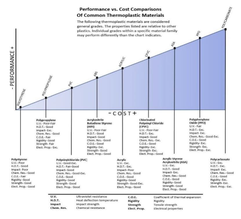
Material Selection
Material choice affects everything from flow behavior to durability. Common extrusion materials include the following:
- Polystyrene (PS)
- Polypropylene (PP)
- Polyvinyl chloride (PVC)
- Acrylonitrile butadiene styrene (ABS)
- Acrylic
- Chlorinated polyvinyl chloride (CPVC)
- Acrylic styrene acrylonitrile (ASA)
- Polyphenylene oxide (PPO)
- Polycarbonate (PC)
Each material has a different melt flow rate, stiffness, and shrinkage profile. These differences influence die design, cooling requirements, and achievable tolerances.
Design tip: Selecting a material without considering its processing behavior often leads to redesigns later.
Cooling & Shrinkage
All extruded materials shrink as they cool. This shrinkage must be accounted for during the design phase to achieve the desired final dimensions.
Cooling rates also affect part stability. Faster cooling can lock in stresses, while slower cooling can improve dimensional accuracy but reduce throughput.
End-Use Considerations
Design decisions should always reflect how the part will actually be used in the real world. It’s not enough for a profile to meet dimensional specs on paper. It must also perform under environmental conditions, mechanical stress, and downstream processing requirements.
Key factors to evaluate early in the design process include the following:
- Application and load conditions: Will the part be structural, decorative, or functional? Will it experience impact, flexing, or continuous stress over time?
- Tolerance requirements: Tight tolerances may be necessary for assembly or fit, but over-specifying them can increase tooling complexity and production cost. Balance precision with manufacturability.
- Surface finish requirements: Cosmetic surfaces, matte finishes, or textured profiles may require adjustments in tooling and processing conditions to achieve the desired look and feel.
- Color requirements: Custom colors can impact material selection and processing stability. Some pigments affect flow characteristics or UV resistance.
- Clarity and transparency: Clear or translucent profiles demand stricter control over material quality, temperature, and contamination to avoid visual defects.
- Secondary operations: Consider whether the part will be cut, drilled, printed, bonded, or assembled after extrusion. These steps may influence material choice, wall thickness, and geometry.
Ignoring end-use requirements often leads to redesigns later, especially when parts fail in assembly or under real-world conditions. A profile that is easy to extrude but not fit for purpose creates downstream problems that are far more expensive to fix. The most effective designs account for both manufacturing constraints and final application from the start, aligning material, geometry, and finishing requirements with how the product will actually be used.
Types of Plastic Extrusion Dies & Tooling
The die is where design intent becomes physical reality. Its configuration controls how material flows, how pressure is distributed, and how consistently the profile forms as it exits the extruder.
There are several types of plastic extrusion dies and tooling setups that manufacturers use, each suited to specific applications.
Flat Die
Flat dies are used for producing sheets and films where thickness across a wide surface must remain uniform. The molten material is distributed laterally inside the die and exits through a controlled gap that sets final thickness.
Flow distribution inside the die is a key challenge, as uneven distribution leads to thickness variation across the width. Designs that require tight thickness control or consistent surface quality benefit from precise die gap adjustment and stable processing conditions.
Round Die
Round dies produce cylindrical shapes such as pipes, tubing, and hoses. These dies have circular openings that shape the plastic into the desired cross-section. The design focuses on maintaining uniform material flow around the full circumference to achieve consistent wall thickness.
Imbalances in flow can quickly lead to ovality or uneven walls. Material selection, die design, and downstream calibration all play a role in keeping the profile stable, especially for thin-wall or tight-tolerance tubing.
Profile Die
Profile dies are custom-built to produce specific, often complex cross-sectional shapes. They are commonly used for window frames, seals, trims, and engineered profiles with specific functional features.
Because of their complexity, profile dies require careful flow balancing to ensure all sections fill evenly. Designs with varying wall thickness, tight corners, or intricate features increase tooling complexity and may require iteration during development to achieve stable production.
Co-Extrusion Die
Co-extrusion allows multiple materials to be combined into a single profile through a shared, double-layer die. This process makes it possible to layer different properties such as rigidity, flexibility, abrasion resistance, or barrier performance into one product.
While powerful, co-extrusion introduces additional complexity. Each material must flow at compatible rates and bond properly at the interface. Poor material pairing or flow imbalance can lead to delamination or inconsistent layer thickness, making early design alignment critical.
Common Materials Used in Plastic Extrusion Tooling
Tooling materials play a critical role in long-term performance, maintenance requirements, and overall production efficiency. The right material must be able to withstand the high temperatures and pressures of the plastic extrusion process while maintaining precise geometry over time.
The most common materials used in the construction of plastic extrusion dies and tooling are tool steel and stainless steel.
Tool Steel
Tool steel offers high strength, excellent wear and heat resistance, and the ability to maintain tight tolerances over extended production runs. It is widely used for high-volume applications and profiles with more complex geometries where dimensional stability is critical.
Because of its durability, tool steel helps reduce deformation and wear over time, which translates to more consistent output and fewer interruptions for maintenance. It’s often the preferred choice when long-term performance and precision are priorities.
Stainless Steel
Stainless steel provides strong corrosion resistance, making it ideal for applications where the plastic extrusion process involves moisture, chemicals, or strict cleanliness requirements. It’s commonly used in medical, food-grade, and specialty applications where contamination or material degradation must be avoided.
While it may not always match tool steel in wear resistance, its ability to maintain integrity in harsh or regulated environments makes it essential for certain industries.
Challenges in Plastic Extrusion Design & Tooling
Even strong profile concepts can run into problems once production begins. In extrusion, small design or tooling issues tend to show up quickly in the form of dimensional variation, cosmetic defects, instability, or unnecessary scrap.
Heat Management
Temperature control is one of the most important variables in extrusion. If the melt is too hot, the material can degrade, lose shape stability, or develop surface defects. If temperatures are too low or inconsistent, flow problems, poor surface finish, and incomplete profile formation can result.
Heat-related issues often show up as melt fracture, roughness, dimensional inconsistency, or instability during cooling.
You can manage this challenge through a combination of proper material selection, stable processing conditions, and profile designs that do not force extreme temperature sensitivity. Cooling must also be considered as part of heat management. A profile that cools unevenly is more likely to warp, bow, or retain internal stress. Designing for balanced wall thickness and controlled cooling improves both manufacturability and final part quality.
Flow Imbalance
Flow imbalance occurs when molten material does not move evenly through the die, which can create thickness variations, distorted geometry, poor surface finish, or inconsistent dimensions along the profile. It is often caused by uneven wall thickness, abrupt geometry changes, tight corners, or die designs that do not distribute pressure evenly.
The best way to reduce flow imbalance is to simplify geometry where possible, maintain more uniform wall sections, and allow for smooth transitions throughout the profile. Proper die design and early collaboration with the extrusion manufacturer are also critical, especially for complex profiles. In many cases, minor design changes made before tooling is cut can prevent major stability issues later.
Die Wear
Die wear is a gradual but serious issue that affects long-term production consistency. As tooling surfaces wear down, the profile can begin to drift out of tolerance, lose surface quality, or require more frequent adjustment during production. Abrasive materials, high production volumes, extreme heat, and inadequate tooling material selection can all accelerate wear.
To reduce die wear, it is important to use tooling materials that match the application, such as tool steel for high-volume or demanding runs. Regular inspection and preventive maintenance also help identify wear before it begins affecting output. When possible, profile designs should avoid unnecessary complexity that places extra stress on specific areas of the die.
Tolerance Limitations
Plastic extrusion can produce highly consistent profiles, but it still has practical tolerance limitations that depend on the material, profile shape, wall thickness, and cooling behavior. When tolerances are tighter than the process can reasonably hold, production becomes more difficult, costs rise, and scrap rates often increase.
To avoid tolerance limitations, specify tolerances based on actual functional requirements rather than defaulting to the tightest possible numbers. Engineers should identify which dimensions are truly critical for fit, sealing, or assembly and allow more flexibility elsewhere.
Additionally, working with a plastic extrusion partner early can help set realistic expectations and avoid overengineering the profile in ways that add cost without improving performance.
Best Practices for Plastic Extrusion Tooling & Design
The following best practices help reduce risk, control cost, and improve production consistency throughout the plastic extrusion process.
Design for Uniform Material Flow
Maintaining consistent wall thickness and smooth transitions throughout the profile helps material flow evenly through the die. Designs that force the material to speed up or slow down abruptly introduce instability, which leads to warping, dimensional variation, and scrap. A balanced profile is easier to produce, easier to control, and more predictable over long production runs.
Simplify Geometry Where Possible
Complex internal features, tight corners, and multi-cavity hollow sections increase tooling complexity and make it harder to maintain dimensional consistency. While some designs require complexity, unnecessary features should be eliminated early. Simpler profiles reduce tooling cost, shorten lead times, and improve overall production stability.
Use Generous Radii to Improve Performance
Sharp edges create stress concentrations and disrupt material flow. Adding larger radii improves how material fills the profile, reduces internal stress, and results in stronger, more durable parts. This small design adjustment can significantly improve both manufacturability and end-use performance.
Select Materials with Processing in Mind
Choosing a material based only on end-use performance often leads to processing challenges that require redesign or compromise later. Material selection should reflect not only performance requirements but also how the material behaves during extrusion. Melt flow rate, shrinkage, and thermal stability all influence how easily a profile can be produced.
Design with Realistic Tolerances
Overly tight tolerances can make a profile difficult and expensive to produce. Not every dimension needs the same level of precision. Focus on critical dimensions required for fit and function, and allow flexibility where possible. This approach improves manufacturability while keeping cost under control.
Account for Cooling & Shrinkage Early
Profiles change as they cool. Ignoring shrinkage and cooling behavior during design can result in parts that do not meet final specifications. Designing for balanced cooling and accounting for material shrinkage helps maintain dimensional accuracy and reduces the need for post-production adjustments.
Collaborate Early with Plastic Extrusion Experts
One of the most effective ways to avoid costly mistakes is to involve plastic extrusion specialists early in the design process. They can identify potential flow issues, tooling challenges, and tolerance risks before production begins. A design that looks correct in CAD may still fail in production, but early input helps bridge that gap and leads to a smoother path from concept to finished part.
Plastic Extrusion Design & Tooling: FAQs
What Tolerances Can Plastic Extrusion Achieve?
Tolerances depend on material, profile complexity, and tooling design. Simpler profiles with stable materials achieve tighter tolerances than complex or hollow designs.
How Do You Prevent Warping in the Plastic Extrusion Process?
To reduce warping in the plastic extrusion process, maintain uniform wall thickness, control cooling rates, and optimize die design.
What Affects Plastic Extrusion Tooling Cost?
Tool complexity, material selection, and profile geometry all influence the cost of plastic extrusion. More complex designs require more precise and expensive tooling.
When Should Co-Extrusion Be Used?
Co-extrusion is ideal when a single material cannot meet all performance requirements, such as combining strength and flexibility in one profile.
How Long Does Plastic Extrusion Tooling Typically Last?
Tooling life depends on the material being processed, production volume, and tooling material. High-quality tool steel dies can run for long production cycles, but regular maintenance and inspection are required to maintain performance and dimensional accuracy.
What Are the Most Common Causes of Plastic Extrusion Defects?
Common defects include warping, surface roughness, dimensional variation, and internal stress. These are often caused by poor flow balance, inconsistent wall thickness, improper temperature control, or inadequate cooling design.
When Is Plastic Extrusion Not the Right Manufacturing Process?
Plastic extrusion is not ideal for parts with complex three-dimensional features, varying cross-sections, or extremely tight tolerances. In those cases, processes like injection molding or machining may be more suitable depending on the application.
Contact Lakeland Plastics: The Leading Plastic Extrusion Company
Plastic extrusion design and tooling play a critical role in determining product performance, production efficiency, and overall cost. By focusing on material behavior, geometry, and manufacturability, engineers can develop profiles that run smoothly and meet real-world demands.
At Lakeland Plastics, we work closely with engineering teams to refine designs before tooling is built, helping avoid costly revisions and production issues. If you are developing a new extrusion profile or optimizing an existing one, our team can help you evaluate your design so you can move forward with confidence.
Contact us or request a quote today to discuss your project and get expert guidance on your plastic extrusion design.